[ Uppsala U. | Signals
and Systems: | Staff
| Research
| Publications
| Education ]
The Adaptive Antenna Testbed
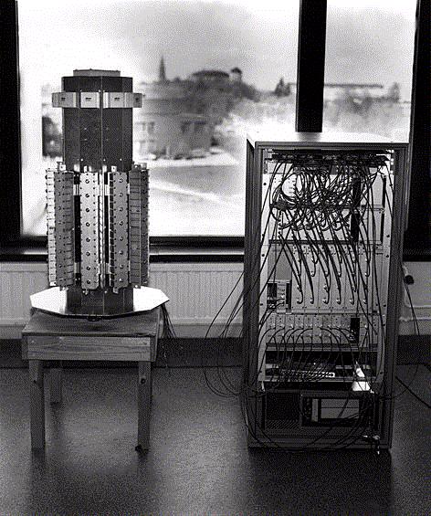
An adaptive antenna for DCS-1800 working in the uplink mode has been designed
and constructed at the Signals and Systems Group in co-operation with Ericsson
Radio Access AB. It has two multiplexing channels allowing for trials
with SDMA. It uses an DCS-1800 basestation as a host for generation of standarized
DCS-1800 (GSM) signals for realistic bit error rate measurements. The architecture
and results from measurements are presented in the conference papers listed
below, and also in a forthcoming licentiate thesis. The picture shows
the antenna array to the left, consisting of ten patch antenna elements situated
in a circular array configuration. To the right is the signal processing rack,
consisting of receivers, A/D converters, weights and a DSP.
Antenna Laboratory Measurements
By performing measurements in the laboratory, the performance of the
adaptive antenna was evaluated, and also the functionality was verified.
The antenna front end was replaced by a 8*8 analog butler matrix to emulate
a linear array with isotrop antenna elements. Two signal generators were
connected to the butler matrix and by varying the carrier and the interferer
power different measurements were made including BER measurements. The
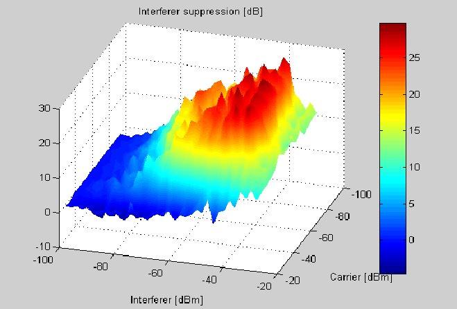
graph below shows thw suppresion of the interfering signal as a function
of its power and the carrier power. This graph verifies the result that
the adaptive antenna supresses the interferer to the noise floor, so the
interferer suppression is increased linearly with incresing interferer
power. However, as also can be seen in the graph, there is a limit of suppression,
this is due to the quantisation of the hardware weights. The weight accuarcy
is 1 dB in amplitude and 1 degree in phase. When the interferer power is
above -30 dBm, the suppression drops abruptly, due to saturation of AD
converters in the receiving chain. For more information, please download
the papers at the end of this page.
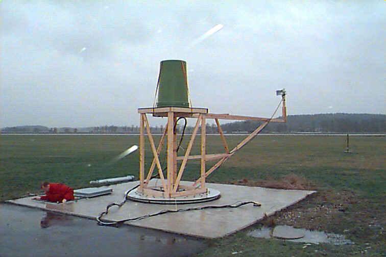
Antenna Field Measurements
To evaluate the adaptive antenna performance in an well defined signal environment,
we went to an antenna measurement range at FFV Aerotech in Arboga, Sweden. Here,
radiation pattern for "easy" scenarios could be measured. The field was open
, so no multipath is present, also the signal sources were stationary, thus
avoiding fading. The antenna front end was mounted on top of a mechanical
turntable, see the figure. The antenna front end was covered with a green plastic
non-conducting "barrel", for weather protection.
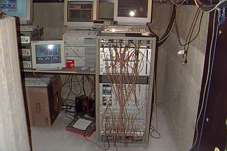
Below the setup there was a room for equipment setup as seen in the picture
below.
Measurements were made on antenna radiation patterns for different power
settings for the desired and interfering signal sources. Also the angle
separating the two signal sources were varied. Radiation patterns are presented
below:
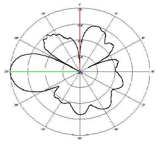
The picture above show the radiation patterns with two signal
sources of equal power, desired direction marked with green and interfering
direction red. As can be seen the adaptive antenna creates a sharp and
deep null against the interfering signal, while the mailobe points at the
desired signal. But what happens if the separation angle gets smaller?
This was investigated as seen below.
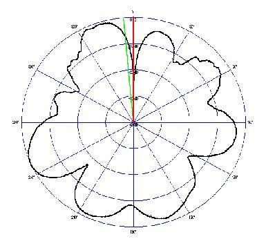
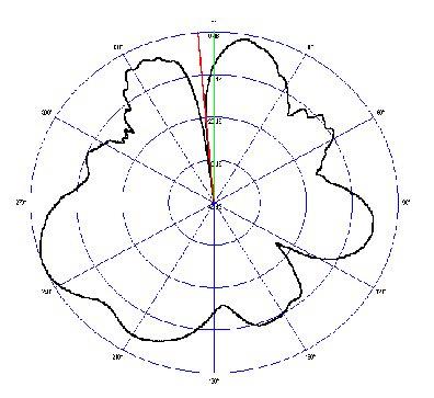
These two radiation patterns shows how the antenna tries to null the interferer
when the angle separation is very narrow, only 5 degrees. It is also interesting
to measure the Bit Error Rate (BER) as a function of separation for the two
mobiles. The results from these measurements can be seen in the figure below.
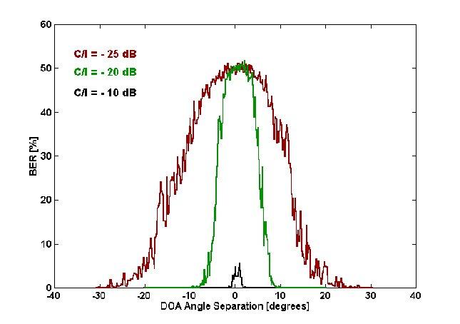
It is interesting to see how the smallest separation angle allowed is
dependent of the C/I impinging on the antenna. For C/I = -20 dB the smallest
separation angle to maintain approximately 0 % of BER is 10 degrees.
[ Uppsala U. | Signals
and Systems: | Staff
| Research
| Publications
| Education
]
webmaster@signal.uu.se
| Updated May 13, 1997 (MS) | www.signal.uu.se/Research/rbasada.html