Microwave Engineering II
Design for maximum gain and constant gain circles and design for specific gain.
We have from the preceding lectures enough basic knowledge to start designing amplifiers. We will go through two kinds of amplifier designs; one where we want the amplifier to have the maximum possible gain, and the other where we specify the amplifier to have a specific gain.
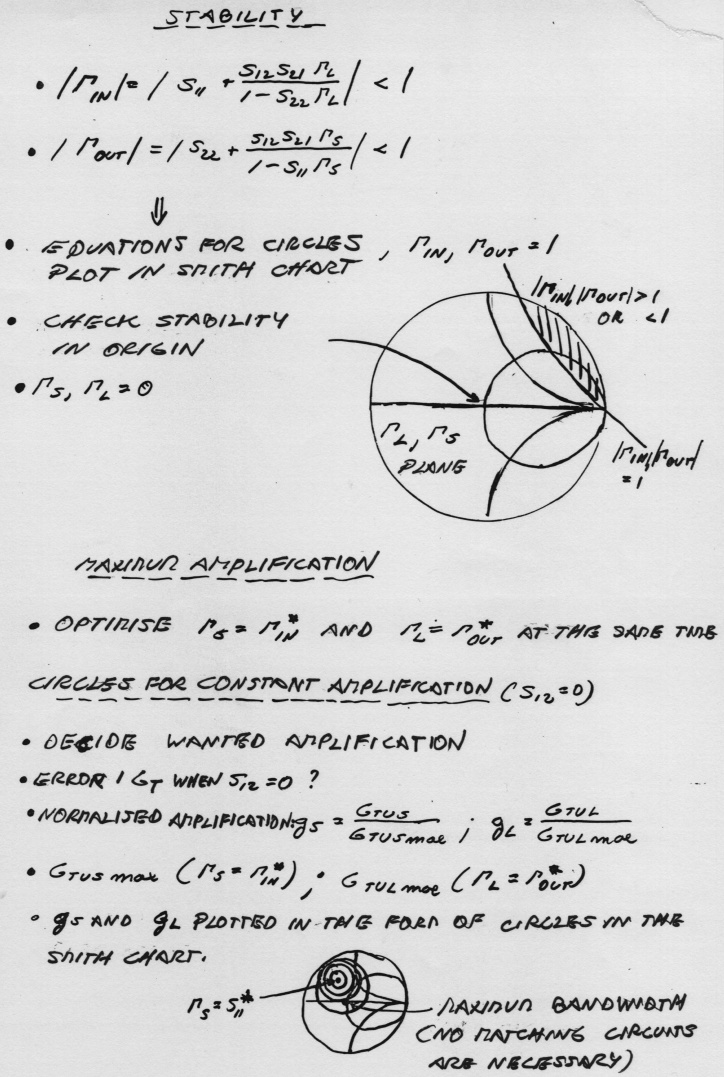
In the first case we will derive the optimum input and output matching impedance's for a non-unilateral device, which means that since the optimum input and the output impedance are depending on each other through the S12 and S21 scattering parameters for the device we need the impedance calculations to be done simultaneously on the input and output, see eq. 11.41a and 11.41b in Pozar. As a result of this procedure we end up having a second order equation which gives us the optimum impedance's for the source and load, see eq. 11.43a and 11.43b. We will find that the optimization for maximum gain will bring the optimum source and load impedance's very close to the input- and output-stability curves respectively and thus increase the risk of turning the amplifier into an oscillator.
Comparing the bandwidth and the gain, see Figures 11.13 and 11.14 in Pozar, for the maximum gain amplifier with the fixed gain one respectively you will see that a smaller gain gives a broad bandwidth. However the input and output matching will not be as good for the maximum gain one, but often good enough to be used in an real application. By having a larger bandwidth we can release the pressure on having the design to be exactly on the spot of the operating frequency.
In this lecture we will also go through how we create using microstrip lines the optimum terminating impedance's that we have calculated for the transistor.
The second case where we specify the gain (below the maximum one) will give us a more stable amplifier and is also the normal procedure in industry for designing amplifiers. Thus, instead of designing the amplifier for maximum gain we instead connect several amplifiers with lower gain in series. The technique that we will go through for designing a fixed gain amplifier is based on that S12 is very small compared to S21, and can thus be put to zero. The error that we get in the design by putting S12 to zero is calculated using the expression for the "the unilateral figure of merit", se eq. 11.46 and 11.47. In the fixed gain design we use the technique of splitting the equation for the transducer gain into the three sections: input, device and output gain. By creating a variable defined as the relation between the maximum gain and the specified one we can calculate and depict the curves in the Smith-chart that defines the selected constant gain.
To study:
Textbook pages: 618-627.
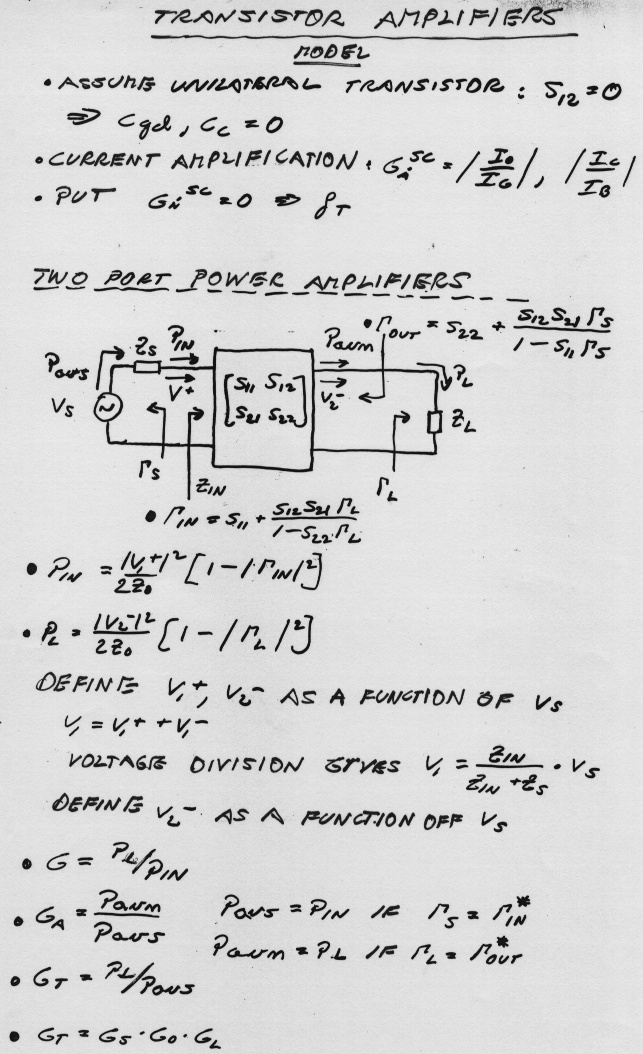
Below find a recapitulation of what we have studied so far on transistor amplifiers


To understand:
Important equations:
Examples:
Example 11.3 and 11.4 in Pozar is solved during the lecture. As homework you can try example 11.3, 11.8, 11.9, 11.10 from the Problem section in Pozar.